Dimensioning requirements for injection molded parts
Dimensioning of injection molded parts is a crucial bridge between design and production. Its standardization directly impacts mold manufacturing accuracy and part assembly performance. Dimensioning must balance design intent, process feasibility, and ease of testing, adhering to the principles of clarity, completeness, and rationality. Compared to mechanical parts, dimensioning of injection molded parts requires full consideration of factors such as plastic shrinkage, mold manufacturing tolerances, and assembly clearances to avoid dimensional deviations or assembly difficulties caused by improper dimensioning.
The completeness of dimension marking requires covering all key dimensions of the part, including external dimensions, internal cavity dimensions, wall thickness, hole dimensions, step height, etc., and each dimension only needs to be marked once to avoid confusion caused by repeated marking. For parts with assembly requirements, the fitting dimensions and their tolerance grades must be clearly marked. For example, the clearance of the shaft-hole fit must be marked as Φ10H7/g6, where H7 is the tolerance band of the hole and g6 is the tolerance band of the shaft, to ensure that it can fit smoothly and meet positioning accuracy during assembly. Free tolerances can be used for non-fitting dimensions, but a reasonable range must be set according to the use scenario of the plastic part. Generally, the free tolerance of appearance parts is controlled within ±0.1mm, and that of structural parts can be relaxed to ±0.2mm. In addition, for curved surfaces or complex contours, coordinate marking or 3D model-assisted marking is required to ensure a clear basis for mold processing.
Considering plastic shrinkage is a special requirement for dimensioning injection molded parts. Shrinkage compensation must be factored into the basic dimensions to ensure that the part meets design requirements after cooling. The shrinkage rates of different plastics vary significantly. For example, the shrinkage rate of PE ranges from 1.5% to 3%, while that of ABS is 0.5% to 1.5%. When dimensioning, the shrinkage rate should be selected based on the specific material and the basic dimensions should be converted to mold dimensions. For example, when designing a square ABS part with a side length of 100mm, the mold dimensions should be marked as 100 × (1 + 1%) = 101mm, and the part dimensions should be marked as 100 ± 0.5mm. For areas requiring high dimensional accuracy, the basis for the shrinkage rate value must be indicated on the drawing, and it is recommended that the mold utilize an adjustable structure to allow for dimensional adjustments based on trial mold results.

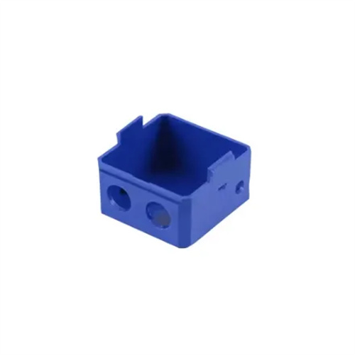
The selection of the datum for dimensioning must follow a unified principle to ensure the coordination between the various dimensions and the accuracy of the measurement. Usually, the symmetrical surface of the part, the assembly datum surface or the larger plane is selected as the primary datum, and the secondary dimensions are marked with reference to the primary datum to avoid forming a closed dimension chain. For example, the height and length dimensions of box-type plastic parts are marked with the bottom and side surfaces as the datum to ensure the positioning consistency with other parts during assembly. For hole systems with assembly relationships, the center distance between each hole and the distance from the datum surface need to be marked. The center distance tolerance is generally controlled within ±0.05mm to ensure the smooth assembly of bolts or shaft parts. Curved parts can use a three-dimensional coordinate datum, and the key points are marked with the coordinate values in the X, Y, and Z directions, and precise processing can be achieved in conjunction with the three-dimensional model.
The marking method must take into account the mold processing technology to avoid marking dimensions that are difficult to achieve or detect through the mold. For structures such as slopes and fillets, the slope value (such as 1:50) or angle (such as 3°) and fillet radius (R0.5) must be marked, and it must be indicated whether it is included in the basic size. The wall thickness marking must clearly state the minimum wall thickness and the maximum wall thickness, and the wall thickness difference of the same part should not be too large, generally controlled within 2:1. The form of “t=2±0.2” can be used when marking, and the wall thickness uniformity requirements must be indicated in the technical requirements. For parts with core pulling or side holes, the distance and angle between the side hole and the reference plane must be marked to facilitate the design of the side core pulling mechanism of the mold. In addition, the measurement temperature of the dimension must be indicated on the drawing, usually 23℃±2℃, to avoid measurement errors caused by temperature changes.
The technical requirements section should supplement special requirements not covered by dimensioning to ensure that the quality of the plastic parts meets the requirements. Unfilled corner radii (e.g., “Unfilled corners R0.3-R0.5”), unfilled slopes (e.g., “Mold draft angle 3°”), and dimension inspection methods (e.g., “Inspected using a 3D measuring instrument”) should be specified. For exterior parts, the surface roughness (e.g., “Ra1.6”) and the allowable defect range (e.g., “Sink marks greater than 0.2mm are not allowed”) should be indicated. For parts requiring assembly interchangeability, the CPK values of important dimensions (e.g., “Critical dimension CPK ≥ 1.33”) should be indicated to ensure the stability of the production process. By combining dimensioning with technical requirements, the production standards of injection molded parts can be fully standardized, reducing communication errors between design and manufacturing.