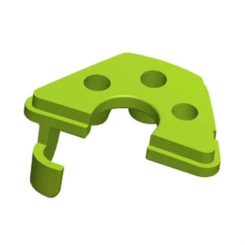
Lateral core pulling mechanism of slider bending pin
The lateral core-pulling mechanism of a slider and bent pin is a crucial device for lateral molding and demolding of plastic parts in injection molds. It utilizes the inclined surface of the bent pin to drive the slider’s lateral movement, completing the core-pulling and reset actions. It is widely used in the molding of plastic parts with complex structures such as side holes, undercuts, and threads. Compared to inclined guide pin core-pulling mechanisms, bent pin core-pulling mechanisms offer greater core-pulling force, a longer core-pulling distance, and a compact structure. They are particularly suitable for large plastic parts or applications with high core-pulling resistance. For example, when molding the mounting clips on the side of an automobile bumper, due to the clip depth of up to 20mm and the strong clamping force of the plastic melt on the core, a bent pin core-pulling mechanism can provide sufficient core-pulling force to ensure smooth demolding.
The lateral core pulling mechanism of a slider’s bent pin primarily consists of a bent pin, slider, guide groove, wedge, and stopper. The precision of the fit of these components directly impacts the smoothness and reliability of the core pulling operation. The bent pin, the core driving component of the mechanism, is typically rectangular or circular in cross-section. Rectangular bent pins offer greater rigidity and are suitable for applications with high core pulling forces, while circular bent pins are easier to process and less expensive. The bent pin’s inclination angle is typically 15°-25°. A smaller angle increases the core pulling distance and mold size, while a larger angle increases the bending forces on the bent pin, potentially leading to deformation or breakage. For example, a mold with a bent pin designed for a 30° inclination experienced repeated bending during the core pulling process. Adjusting the angle to 20° resolved the issue. The clearance between the slider and guide groove must be strictly controlled, typically within a range of 0.02-0.05mm, to ensure smooth, non-binding movement of the slider.

The operation of the lateral core-pulling mechanism of the slider’s bent pin can be divided into two stages: core-pulling and reset. During mold opening, the movable mold separates from the fixed mold, and the bent pin, fixed to the fixed mold, moves with it. Its inclined surface forces the slider to move laterally along the guide groove, achieving core-pulling. When the mold opens a certain distance, the slider is completely separated from the plastic part. At this point, a stop device (such as a stop pin or spring) secures the slider at the end of core-pulling, preventing it from moving under the influence of gravity. During mold closing, the other side of the bent pin pushes the slider in the opposite direction, resets it, and simultaneously locks the slider with a wedge to prevent displacement due to the pressure of the plastic melt during injection molding. For example, in the bent pin core-pulling mechanism of a home appliance housing mold, the slider completes a 15mm core-pulling distance when the mold opening stroke reaches 100mm. During mold closing, the bent pin accurately resets the slider, and the wedge engages the contact surface of the slider, ensuring secure mold locking.
When designing the lateral core-pulling mechanism for a slider’s bent pin, the calculation of the core-pulling force and distance is crucial. The core-pulling force depends on the part’s core-to-core clamping force, the part’s geometry, and the plastic’s properties. The calculation formula is: F = K × A × σ, where F is the core-pulling force (N), K is the safety factor (typically 1.2-1.5), A is the core-to-part contact area (mm²), and σ is the plastic’s clamping stress (MPa, typically 2-8 MPa). For example, if a part has a core contact area of 500 mm² and is made of ABS plastic (σ = 4 MPa), the core-pulling force F = 1.3 × 500 × 4 = 2600 N. The core-pulling distance must be greater than the depth of the part’s side hole or undercut, typically 2-3 mm greater than the actual depth, to ensure smooth demolding. For example, if the undercut is 8 mm deep, the core-pulling distance should be designed to be 10-11 mm.
Common issues and solutions for the lateral core-pulling mechanism of the slider’s bent pin also require significant design attention. Unsteady slider movement during core-pulling is often due to poor lubrication of the guide slot or insufficient clearance. This can be addressed by adding grease or grinding the guide slot to adjust the clearance. Bend pin breakage can be caused by an excessively large tilt angle or insufficient pin strength. This requires reducing the tilt angle or selecting a high-strength material (such as quenched 40Cr steel) for the pin. Inaccurate slider resetting is often due to an excessive clearance between the pin and the slider or a failed stop. These issues can be addressed by replacing worn parts or adjusting the stop position. For example, during production, a mold experienced slider resetting deviation. Inspection revealed that this was due to increased clearance caused by worn bend pins. Replacing a new bend pin restored resetting accuracy. Through proper design and timely maintenance, the slider’s bent pin’s lateral core-pulling mechanism can reliably and stably perform core pulling, ensuring part quality.