Location of injection gate
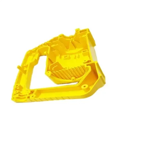
The selection of injection molding gate location is a critical step in mold design that determines the quality of plastic parts. It directly affects the plastic melt’s filling path, pressure distribution, pressure holding effect, and residual stress. A reasonable gate location can significantly reduce defects such as warping, sink marks, and weld marks. The gate location should adhere to the “thick near, thin far” principle, meaning it should be prioritized in areas with thicker walls. This allows the melt’s flow inertia in the thicker areas to propel the thinner sections, avoiding underfilling due to excessive pressure loss. For example, a mobile phone battery cover has a main body wall thickness of 2mm and an edge wall thickness of 0.8mm. Placing the gate in the thick center of the main body allows the melt to first fill the thicker wall area before flowing toward the thinner edge sections. This reduces filling time by 8% and completely eliminates edge underfilling.
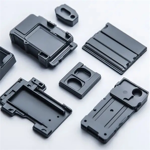
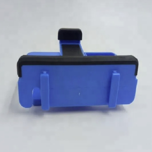
The gate location should try to avoid weld marks or place weld marks in non-stressed areas. When a plastic part has multiple cavities or a complex structure, the melt may fill in from different directions and form weld marks at the intersection. The strength of the weld marks is usually 60%-80% of the plastic part itself. If the weld marks are in a stressed area, it can easily cause the part to break. By setting the gate in an area where the melt can reach all weld mark locations at the same time, the number of weld marks and the difference in their strength can be reduced. For example, a square plastic part uses a central single-point gate, and the melt radiates outwards to form symmetrical weld marks at the four corners. All of these are in non-stressed corners. After testing, their tensile strength reaches 85% of the part itself. However, when a side gate is used, the weld marks appear in the stressed area in the center of the long side, and the strength is only 65% of the part itself, which cannot meet the requirements of use.
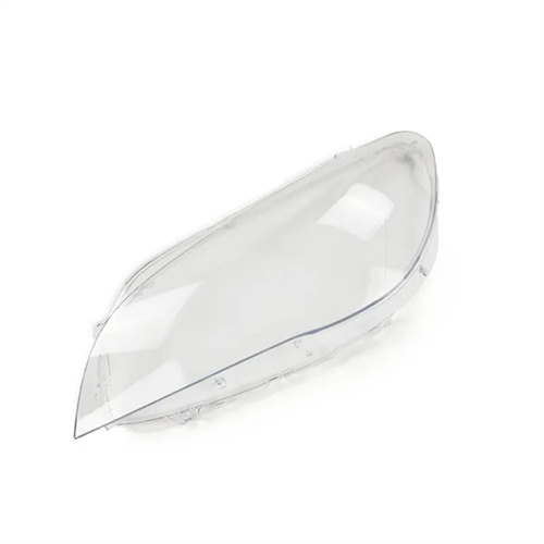
The gate location should take into account the appearance quality of the plastic part. Avoid placing gates on visible or decorative surfaces to prevent gate marks from affecting the aesthetics. For plastic parts with high appearance requirements, such as automotive interiors and home appliance panels, latent gates or point gates can be used. Latent gates are placed on the inside or edge of the plastic part, and the gate marks are hidden on non-visible surfaces. Point gates typically have a diameter of 0.8-2mm, and the marks are small after removal, which can be processed through later polishing. For example, the front of a refrigerator door panel has a high-gloss mirror finish. Placing the gate as a latent gate on the reinforcing rib on the back of the door panel eliminates any gate marks on the front, and the appearance qualification rate increases from 82% to 99%. At the same time, the gate location should be away from the mating surfaces of the plastic part with high precision requirements to avoid dimensional deviations due to uneven holding pressure.
The choice of gate location must be tailored to the plastic’s flow characteristics. For plastics with poor flow properties (such as polycarbonate and polyvinyl chloride), the melt flow path should be shortened, and the gate should be placed closest to the farthest filling point to minimize pressure loss. For plastics whose viscosity is sensitive to shear rate (such as polyethylene and polypropylene), the flow path can be appropriately increased to utilize the shear-thinning effect to improve flow properties. For example, a polycarbonate lampshade part, 300mm long, would experience insufficient melt flow pressure at the end of the flow, leading to material shortages, if a single-sided gate was used. By switching to symmetrical dual gates at both ends, the flow path was shortened to 150mm, reducing pressure loss by 40%, fully meeting filling requirements. Furthermore, for glass-fiber-reinforced plastics, gate location affects glass fiber orientation. Placing the gate in a position that aligns the glass fibers along the direction of force can improve part strength.
Innovative gate placement is required for parts with specialized structures. For slender rod-like parts, multiple gates are used along the length to ensure segmented filling of the melt and minimize bending deformation. For deep-cavity parts, a bottom center gate is used to leverage the melt’s gravity to assist filling and reduce clamping force requirements. For parts with metal inserts, the gate should be positioned away from the insert to avoid direct impact of the melt, which can lead to stress concentration and displacement. For example, in a plastic gear with a copper insert, the gate is positioned at the gear hub, away from the insert-plastic interface. This keeps insert displacement within 0.01mm, far below the design requirement of 0.03mm. CAE mold flow analysis software can simulate the filling effects of different gate positions, predict defect locations, and provide a scientific basis for optimizing gate placement. Currently, mainstream software can achieve simulation errors within 5%, significantly improving gate design accuracy.