Cavity arrangement of injection molds
The cavity arrangement of the injection mold is a key link in the design of multi-cavity molds. It directly affects the mold size, melt flow balance, molding efficiency and product quality. It needs to comprehensively consider the product structure, injection molding machine parameters and production needs for scientific planning. The core principle of cavity arrangement is “symmetrical balance”, that is, the distribution of the cavities in the mold must be symmetrical around the center of the main channel to ensure that the distance and resistance of the melt through the branch channel to each cavity are consistent, avoiding uneven product size due to differences in filling time. For example, for small products with four cavities in one mold, a cross-symmetrical arrangement is often used. The four cavities are located around the main channel, and the branch channel length and cross-sectional dimensions are exactly the same to ensure that the melt fills each cavity at the same time and reduce weight deviation.
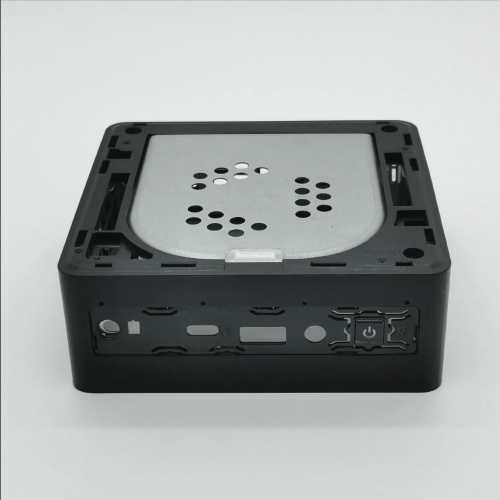
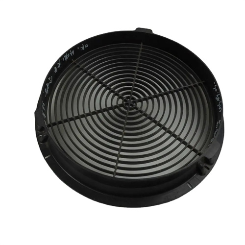
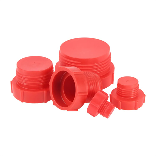
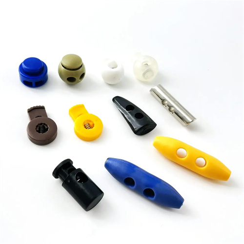
The cavity arrangement method needs to be selected according to the shape and quantity of the product. Common arrangements include circular arrangement, rectangular arrangement, and linear arrangement. Circular arrangement is suitable for small products with a large number of cavities (such as 8 cavities or 16 cavities). The cavities are evenly distributed along the circumference, and the runners are radial. For example, bottle cap molds often use this arrangement, which can fully utilize the mold space and reduce the mold diameter. Rectangular arrangement is suitable for medium-sized products. The cavities are neatly distributed in rows and columns, which is convenient for mold processing and cooling system layout. For example, mobile phone case molds often use 2×2 or 3×3 rectangular arrangements, and cooling water channels can be independently set around each cavity. Linear arrangement is suitable for long strip products. The cavities are distributed along a straight line, and the runners are a single straight line. For example, pen holder molds use this method, which simplifies runner processing and reduces mold complexity.
The cavity spacing must balance mold strength and processing ease. Too small a spacing can lead to insufficient mold strength and deformation under clamping force. Too large a spacing increases mold size, wastes material, and exceeds the mold capacity of the injection molding machine. Typically, cavity spacing is 1.5-2 times the maximum overall dimension of the part, and should be no less than 15mm. For example, for a square part with a side length of 20mm, the cavity spacing should be 30-40mm to ensure sufficient space between cavities for cooling channels and fixing screws. For cavities with side core pulls or complex structures, the spacing should be increased appropriately to reserve space for the core pulling mechanism. For example, for cavities with sloping tops, the spacing should be 5-10mm larger than for standard cavities to prevent interference during core pulling.
The cavity arrangement and gating system design need to be optimized in coordination to ensure balanced melt flow. When the number of cavities is large or the product structure is asymmetric, a balanced runner design is required to compensate for the melt flow difference by adjusting the cross-sectional dimensions (such as length and diameter) of the runner. For example, for an asymmetric product with eight cavities in one mold, the diameter of the runner in the cavity farther away from the main runner can be increased by 0.5-1mm to reduce flow resistance and ensure filling balance. For large multi-cavity molds, a hot runner system can be used. Each cavity is independently equipped with a gate. The temperature control of the hot runner plate ensures that the melt state of each gate is consistent, eliminating the imbalance problem caused by the runner. However, the cost is relatively high and it is suitable for mass production.
Cavity arrangement also needs to consider mold installation and ease of operation. The overall mold dimensions after arrangement must match the tie-bar spacing of the injection molding machine to avoid mold installation problems or insufficient operating space. For example, if the tie-bar spacing of an injection molding machine is 500×500mm, the maximum mold dimensions should be within 480×480mm. The cavity arrangement should facilitate part removal. For molds with manual removal, the cavities should be located in areas easily accessible to the operator. For molds with automatic removal, the cavity arrangement should align with the robot’s motion trajectory to ensure smooth removal. Furthermore, the cavity arrangement should facilitate mold maintenance and repair, leaving ample space for the removal and replacement of cavity inserts. For example, lifting holes and removal slots should be provided around the cavity to facilitate subsequent maintenance. A scientific and rational cavity arrangement design can improve mold production efficiency and stability, while reducing production costs.