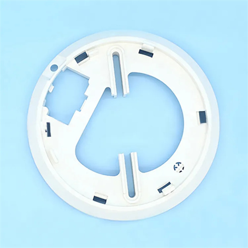
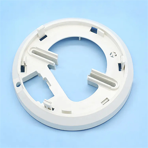
Design of straight-through cooling water channel for injection molding
Injection molding straight-through cooling channels are the most common structure in mold cooling systems. They utilize straight holes machined into the mold plate or core as cooling medium channels, using circulating water or oil to remove mold heat and achieve uniform cavity temperature control. They are widely used in small and medium-sized molds with simple structures. Compared to complex, irregularly shaped cooling channels, straight-through channels offer the advantages of simple processing, low cost, and easy maintenance. For example, in molds for flat-plate products, symmetrically arranging multiple straight-through channels within the cavity and core can quickly dissipate the heat released by the solidified melt, shortening the molding cycle and improving production efficiency.

The layout design of straight-through cooling water channels must follow the principle of “even distribution and close to the cavity” to ensure consistent temperatures in all areas of the mold. The water channels should be evenly distributed along the contour of the cavity, and the distance from the cavity surface is usually 1.5-3 times the diameter of the water channel. For example, a water channel with a diameter of 10mm is 15-30mm away from the cavity surface, which ensures cooling efficiency while avoiding weakening the strength of the mold. For rectangular cavities, water channels can be arranged parallel to the long and short sides with a spacing of 50-100mm; for circular cavities, annular or radial distribution is adopted to ensure uniform cooling at all points. The inlet and outlet of the water channel need to be set symmetrically to avoid the formation of dead zones in the channel by the cooling medium. For example, the inlet and outlet are located on both sides of the mold, so that water flows in from one end and out from the other end, forming smooth convection and improving heat exchange efficiency.
The diameter and number of water channels should be determined based on mold size and heat requirements. Typical diameters range from 8-16mm. Small molds (cavity size <200mm) use 8-10mm, while large molds (cavity size >500mm) use 12-16mm. A diameter too small can easily clog, while a diameter too large takes up mold space and increases processing difficulty. The number of water channels must ensure sufficient cooling area. The calculation formula is: Cooling area = projected area of part × (3-5). For example, if the projected area of a part is 100cm², the cooling area required is 300-500cm². The number of water channels should be determined accordingly. Furthermore, water channels must avoid other mold components, such as ejectors, guide posts, and screw holes. The distance from these components should be at least 1.5 times the water channel diameter to prevent interference. For example, a 10mm diameter water channel should be at least 15mm away from the ejector.
The design of the inlet and outlet water flow of straight-through cooling water channels affects the uniformity of the cooling effect. Common connection methods are series and parallel. The series method connects multiple water channels in sequence, with the cooling medium flowing into the first channel and exiting the last channel after passing through multiple channels. This method is suitable for small molds and has the advantage of a simple structure. However, the disadvantage is a large temperature difference between the inlet and outlet (usually > 5°C), which can lead to uneven mold temperature. The parallel method connects multiple water channels to the inlet and outlet mains simultaneously, with the cooling medium flowing into each channel and then reuniting to flow out. This method is suitable for large and medium-sized molds and can ensure consistent water inlet temperatures (temperature difference < 2°C) in each channel, resulting in good cooling uniformity. However, the piping connection is complex. The connection method should be selected according to the size of the mold during design. For temperature-sensitive plastics (such as PC and PMMA), the parallel method is preferred to avoid product warping due to temperature differences.
Detailed design and maintenance of straight-through cooling channels are crucial to cooling efficiency. Channel bends should be rounded (radius ≥ 5mm) to avoid increased flow resistance and localized turbulence caused by right-angle turns, which can affect flow rate and cooling efficiency. Standard faucets (such as DME and HASCO specifications) should be installed at both ends of the channel to ensure a good seal and prevent leaks. The connection between the faucet and the channel should be sealed with threaded seals (such as NPT or PT threads) and wrapped with raw tape or an O-ring. Regularly clean the channels of scale and impurities. This can be done monthly by circulating a citric acid solution (5-10%) for 30 minutes to remove scale. Annually inspect the channels for blockages and leaks. Severely clogged channels should be cleared through drilling or ultrasonic cleaning. Furthermore, the cooling time and media flow rate should be adjusted based on the plastic type and molding cycle. For example, when molding thick-walled products, the cooling time should be extended (20-30 seconds) and the flow rate should be increased (5-10 L/min) to ensure sufficient cooling and finalization. Through scientific design and standardized maintenance, the straight-through cooling water channel can effectively control the mold temperature and ensure stable product quality.