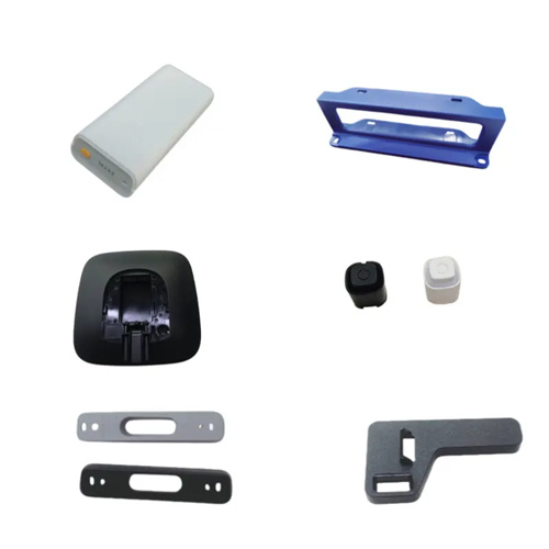
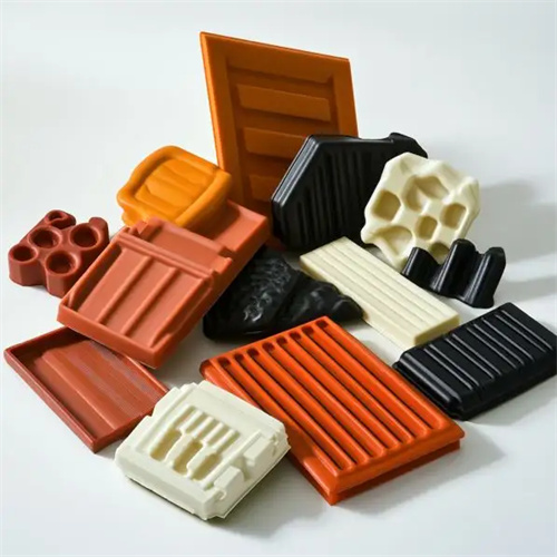
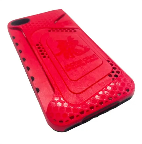
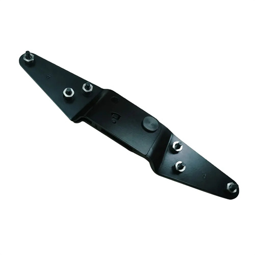
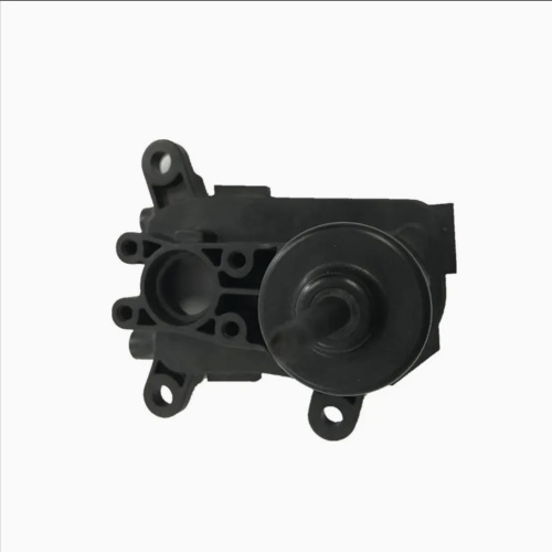
Assembly of injection mold core
As the core molding component of the mold, the injection molding core’s assembly accuracy directly impacts the dimensional accuracy and surface quality of the finished product. The assembly process must adhere to strict procedures and specifications to ensure accurate core positioning and secure fixation. Pre-assembly preparation is essential for ensuring assembly quality. First, the core must be thoroughly inspected for dimensional accuracy, surface roughness, and any deformation or damage. In particular, the molded surface finish must meet requirements to avoid scratches and burrs that could degrade the finished product. Furthermore, the core mounting holes on the mold template must be cleaned to remove any impurities such as oil, iron filings, and other impurities. A dial indicator should be used to check the perpendicularity and coaxiality of the mounting holes to ensure the fit within the designed tolerances (typically an H7/m6 transition fit). For cores with cooling waterways, the waterways must be unobstructed and the seals must be intact to prevent leaks after assembly.
Positioning and pre-fixing the core are critical steps in assembly. Ensure that the core’s position in the mold meets the drawing requirements. For small cores, locating pins can be used to assist with positioning. Locating holes can be machined on the bottom or side of the core, precisely aligning with the locating pins on the template to limit the core’s radial movement. Large cores require positioning with stoppers, using the core’s steps to mate with the stoppers on the template to ensure axial and radial positioning accuracy. During pre-fixing, manually tighten 1-2 set screws to ensure a close fit between the core and the template. Then, use a dial indicator to check the core’s verticality (usually ≤0.01mm/100mm) and flatness. Any deviations can be corrected by tapping the side of the core or adjusting the screws. For modular cores, check the clearances between the individual pieces to ensure a smooth, non-misaligned assembly.
The fastening and force balance of the core directly impact the mold’s service life. The fastening method should be selected based on the core size and stress conditions. Small cores are typically secured from the bottom with hexagon socket screws. The screw specifications must meet strength requirements (e.g., M4-M8, calculated based on the core weight), and the tightening torque must be uniform to prevent deformation of the core due to localized excessive force. Large cores, in addition to bottom screws, also require side clamps or wedges to prevent displacement caused by melt pressure during injection molding. During the tightening process, the screws should be tightened gradually in a diagonal sequence to ensure even contact between the core and the mold plate, with a clearance of no more than 0.005mm. A feeler gauge can be used to check the fit to avoid any gaps. Cores subject to significant lateral forces (such as core-pulling cores) should also be equipped with thrust stops to prevent tilting during operation.
The coordination and adjustment of the core with other components is an important step in assembly, and the coordination of movement with the cavity, push rod, ejector and other components must be ensured. The clearance between the core and the cavity must be strictly controlled. For parts without matching requirements, the clearance can be appropriately widened (such as 0.05-0.1mm), but for the matching of the molding sealing surface, the clearance must be ≤0.01mm to prevent melt overflow. When assembling the push rod, it is necessary to ensure that the push rod is coaxial with the push rod hole on the core, with a matching clearance of 0.01-0.03mm, and the top of the push rod is flush with the molding surface of the core, with an error of no more than 0.01mm, to avoid scratching the product during ejection. For cores with core pulling mechanisms, it is necessary to check the relative position of the core pulling action and the core to ensure that there is no interference during the core pulling process, and that the matching accuracy of the core and the cavity meets the requirements after the core is pulled into place.
Post-assembly inspection and mold trial verification are the final steps to ensure that the core assembly is qualified. First, static inspection is carried out, using a three-dimensional coordinate measuring machine to detect the deviation between the actual position of the core and the designed position. The positioning error of the key dimensions must be ≤0.02mm; then the mold is manually closed to check the fit between the core and the cavity to ensure that there is no jamming or collision. During the mold trial, the molding quality of the product is observed, focusing on the dimensional accuracy, surface finish, and presence of burrs and sink marks of the core molding part. If there is a dimensional deviation, it may be that the core is not positioned correctly; if there are scratches on the surface, it is necessary to check whether there is friction between the core and the cavity. After the mold trial, the core position is fine-tuned according to the quality of the product. If necessary, it is disassembled and the assembly error is corrected until it meets the production requirements. Through strict assembly processes and testing standards, the working stability of the core can be guaranteed and the service life of the mold can be extended.