Fixed mold demoulding driven by hydraulic cylinder
Fixed mold demolding driven by a hydraulic cylinder is a flexible and efficient demolding method suitable for molds with undercuts on the fixed mold side, deep cavities, or products that easily stick to the fixed mold. Its core is to use a hydraulic cylinder to power the demolding mechanism (such as push plates and push rods) on the fixed mold side to release the product from the fixed mold. Compared with traditional movable mold demolding, this method offers the advantages of high demolding force, controllable stroke, and flexible movement. For example, when molding an automotive instrument panel with an undercut on the inner side of the fixed mold side, the hydraulic cylinder can drive the fixed mold core-pulling mechanism to complete the core pulling, and then use the push plate to push the product out of the fixed mold, preventing deformation during the demolding process. This method is particularly suitable for the production of large or complex products.
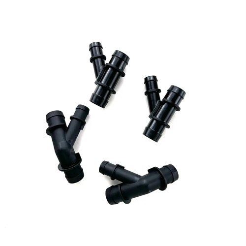
This demolding method consists of a hydraulic cylinder, demolding mechanism, guide device, and control system. The hydraulic cylinder is the power source. The appropriate cylinder diameter and stroke are selected based on the required demolding force. Double-acting cylinders are typically used, capable of both demolding and reset. Operating pressures of 10-15 MPa meet most demolding requirements. The cylinder is mounted on the fixed die base plate or platen and connected to the demolding mechanism via a piston rod to transmit power. The demolding mechanism is selected based on the product structure. A push-plate type is suitable for large-area products, a push-rod type is suitable for partial demolding, and a tilting lift type is used when there is an undercut on the fixed die side. The mechanism must possess sufficient rigidity to prevent deformation under load. Guide devices (such as guide pins and guide sleeves) ensure smooth movement of the demolding mechanism and prevent unbalanced loading. The clearance between the guide pins and guide sleeves is 0.01-0.03 mm, and the surface is hardened for improved wear resistance. The control system controls the cylinder’s motion via a solenoid reversing valve, which is linked to the injection molding machine’s mold open and close signals to achieve automated demolding.
The hydraulic cylinder-driven ejection process for the fixed mold must be coordinated with the mold opening and closing movements to ensure accurate timing. During mold opening, the injection molding machine retracts the movable mold. When the mold has opened to a set distance (usually 1.5 times the product height), the control system sends a signal to activate the hydraulic cylinder, extending the piston rod, which activates the fixed mold ejection mechanism. A push plate or push rod pushes the product out of the fixed mold cavity. Once ejected, the cylinder maintains pressure for 1-2 seconds to ensure the product is completely free of the fixed mold. The cylinder piston rod then retracts, resetting the ejection mechanism. Finally, the movable mold continues to retreat to the mold opening endpoint, where the robot removes the product. During mold closing, the cylinder is in its reset position, allowing the fixed mold ejection mechanism to engage the fixed mold without affecting mold closure. The entire process is precisely controlled by travel switches or displacement sensors to ensure reliable ejection. For example, the ejection stroke should be 2-5mm greater than the product’s clamping depth on the fixed mold side to ensure complete ejection.
The hydraulic system design for this demolding method must meet the required demolding force and speed while ensuring smooth operation. The system requires components such as a hydraulic pump, a reversing valve, a flow valve, and a pressure valve. The flow valve controls the cylinder’s movement speed (typically 50-100 mm/s) to prevent excessive speed from causing impact deformation of the product. The pressure valve sets the demolding pressure, calculated based on the product’s clamping force, typically between 5-10 MPa. Excessive pressure can damage the product, while too low can prevent demolding. The system must include a buffer device to decelerate at the end of the cylinder’s stroke to reduce impact and protect the mechanism. Furthermore, the hydraulic oil must be kept clean and filtered to a minimum of 10 μm. The hydraulic oil should be replaced regularly (every six months) to prevent contamination that could cause cylinder jamming or leakage. For large molds, synchronized multi-cylinder control can be implemented, with flow diverters and combiners ensuring consistent movement of each cylinder to prevent deflection of the demolding mechanism.
Hydraulic cylinder-driven fixed mold release requires several key considerations during design and operation to ensure reliability. Cylinders must be installed symmetrically to avoid uneven force on the release mechanism. For example, a large push plate requires at least two cylinders, symmetrically arranged along the central axis. Floating joints should be used between the cylinders and the release mechanism to compensate for installation errors and prevent radial forces on the cylinders. The strength of the release mechanism must be fully verified. The push plate thickness is calculated based on the release force and is typically no less than 20mm. 45 steel or Q235 steel should be used to ensure rigidity. The push rod diameter should be calculated based on the force to avoid bending and deformation. For example, a 10mm diameter push rod can withstand a release force of approximately 5kN. During routine maintenance, cylinder seals should be regularly checked for aging and leakage, guide lubrication, and control system signals to ensure stable release. Through proper design and maintenance, this release method can effectively resolve the problem of fixed mold release and improve the production efficiency and quality of complex products.