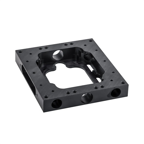
Injection molding ejector plate demoulding mechanism
The injection molding ejector plate demolding mechanism is a commonly used method for demolding products with deep cavities, thin walls, or complex shapes. It uses a single ejector plate to push the product from the core as a whole, resulting in uniform demolding force and a less prone to product deformation. The ejector plate typically contacts the end face or stepped surface of the product and moves along the core axis during demolding, relying on the planar pressure of the ejector plate to free the product from the core. It is suitable for flexible plastics such as polyethylene and polypropylene. Compared to ejector rod demolding mechanisms, ejector plate demolding mechanisms effectively prevent ejection marks on the product surface, improving the product’s appearance quality. Therefore, it is widely used in applications requiring high surface quality, such as automotive interiors and appliance housings.
The structural design of the ejector plate’s demolding mechanism must prioritize the precision of the fit between the ejector plate and the core. Excessive clearance between the two can easily lead to flash on the product, while too small a clearance increases resistance to movement and can even cause scratches. Typically, the fit clearance should be controlled between 0.02-0.05mm. For high-precision products, the clearance can be reduced to 0.01-0.03mm. The design of the ejector plate’s guide mechanism is equally important. A combination of guide posts and guide sleeves is typically used to ensure smooth movement of the ejector plate and avoid deviation or collision with the core. Additionally, avoidance holes must be provided on the ejector plate to avoid other mold components, such as reset rods and tie rods. A sealing structure must also be provided on the contact surface between the ejector plate and the mold cavity to prevent overflow of the plastic melt and ensure the molding accuracy of the product.
The method of transmitting the driving force of the push plate is the core of the mechanism design. Common drive methods include hydraulic cylinder drive, pneumatic cylinder drive, and mold opening force drive. Hydraulic cylinder drive is suitable for situations where a large demolding force is required. The movement speed and stroke of the push plate can be controlled by adjusting the pressure and flow of the hydraulic system. Pneumatic cylinder drive is suitable for small molds or lightweight products and has the advantages of fast response speed and simple structure. Mold opening force drive drives the push plate through the opening and closing of the mold, eliminating the need for additional power devices and reducing mold costs. However, the demolding force and stroke are limited by the mold opening mechanism. When designing the driving force transmission structure, it is necessary to ensure uniform force transmission to avoid deformation of the push plate due to uneven force, which affects the demolding effect.
The reset design of the ejector plate demoulding mechanism is key to ensuring the normal cycle of the mold. The main reset methods include spring reset, tie rod reset, and cam reset. The spring reset structure is simple, and the restoring force is provided by a spring installed between the ejector plate and the mold base, which is suitable for small molds. The tie rod reset uses a tie rod fixed to the mold fixed mold to pull the ejector plate to reset, with high reset accuracy, and is suitable for large molds. The cam reset relies on the cam mechanism during the mold opening and closing process to drive the ejector plate to reset, and is suitable for demoulding mechanisms with complex motion trajectories. The reset design must ensure that the ejector plate can accurately return to its initial position and fit tightly with the mold cavity to avoid affecting the next injection molding. At the same time, the installation position of the reset mechanism must avoid the product molding area to prevent interference with product quality.
The design of the push plate demoulding mechanism must consider the structural characteristics and material properties of the product and perform targeted optimization. For products with undercuts or raised structures, corresponding avoidance or core-pulling structures can be set on the push plate to avoid damage to the product during demoulding. For plastics that are prone to mold adhesion, such as polyvinyl chloride, exhaust grooves can be set on the contact surface between the push plate and the product to reduce the vacuum adsorption force during demoulding. At the same time, a release agent can be applied to the surface of the push plate to reduce frictional resistance. After the design is completed, the demoulding effect of the mechanism must be verified through a trial mold to check whether the product has defects such as deformation, scratches, or residue. Based on the trial mold results, the structural parameters of the push plate, such as movement speed, stroke, and fitting clearance, can be adjusted to ensure that the demoulding mechanism can meet the requirements of mass production.