Injection molding drawing dimensions, title bar and modification bar
As an important technical document for injection molding production, the dimension specifications of injection molding drawings directly affect the production accuracy and assembly performance of the products. Therefore, they must be accurate, clear and standardized. The dimension specification marking must include the key dimensions of the product, such as length, width, height, aperture, wall thickness, etc. For dimensions with matching requirements, the tolerance range must also be marked. The determination of tolerances should be based on the use scenario and assembly accuracy requirements of the product, and refer to relevant national standards or industry standards. For example, for shaft hole structures that require close fitting, the tolerance grade may need to reach IT7-IT8, while for non-matching dimensions, the tolerance can be appropriately relaxed to IT12-IT14. In terms of marking method, clear arrows should be used to point to the marked parts, and the dimension numbers should be filled in above or to the left of the dimension line to avoid overlapping with other lines. For complex structures, detailed marking can be done using partial enlarged views or sectional views to ensure that the operator can accurately understand.
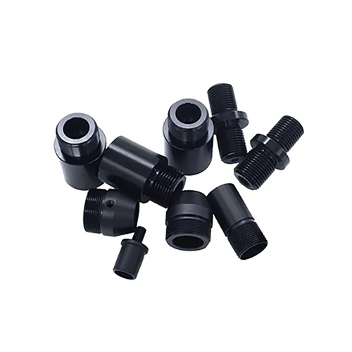
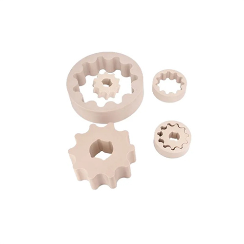
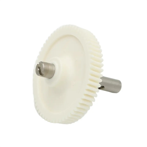
When marking dimensions, attention should also be paid to the uniformity of wall thickness. Uneven wall thickness of injection molded products can lead to inconsistent cooling rates, resulting in defects such as internal stress, shrinkage marks, or warping. Therefore, the wall thickness of each part must be clearly marked on the drawing. For areas with varying wall thickness, the size of the transition fillet must be marked to ensure smooth melt flow and uniform cooling. In addition, for products with special structures such as threads, gears, and splines, the corresponding standard codes and parameters, such as the nominal diameter, pitch, and tooth profile of the thread, must be marked to facilitate the selection of appropriate processing tools and process parameters during production. At the same time, the marking of dimensions should avoid duplication or contradiction. The dimensions of the same point, line, or surface can only be marked once to ensure the uniqueness and accuracy of the drawing.
The title bar is an indispensable component of injection molding drawings. It centrally reflects the basic information of the drawings and facilitates their management and use. The title bar is usually located in the lower right corner of the drawing and its content should include information such as the product name, drawing number, specification model, material brand, scale, weight, drawing date, designer, reviewer, and approver. The product name must accurately reflect the purpose and structural characteristics of the product. The drawing number should be compiled in accordance with the company’s drawing numbering rules and be unique for easy archiving and retrieval. The marking of the material brand is crucial. It directly determines the raw materials used in injection molding production, such as ABS, PP, PC, etc. Different materials have different molding properties, so they must be accurate. The scale marking is used to indicate the proportional relationship between the drawing size and the actual product size. For large products, a reduced scale may be required, while for small and precise products, an enlarged scale may be used for clear drawing.
The signature section in the title block is also crucial. The signatures of the designer, reviewer, and approver not only demonstrate responsibility for the drawing’s quality but also serve as a crucial basis for clarifying responsibilities. Designers are responsible for the structural rationality and dimensional accuracy of the drawing; reviewers review the drawing’s technical feasibility and standard compliance; and approvers confirm the drawing’s ultimate validity. Additionally, the title block can include additional information as needed, such as the client name, project number, and version number, to facilitate communication with the client and project management. The title block should be standardized, with a moderate font size and neat layout to ensure clear and easy-to-read information.
The revision column is a crucial component of version management and change logging for injection molding drawings during use. It clearly reflects the revision history of the drawing, ensuring that the latest and most accurate drawings are used during production. The revision column is typically located to the right of the drawing or above the title bar. It should include information such as the revision number, revision date, revision details, editor, and reviewer. Each revision to a drawing should be assigned a sequential revision number, such as 01, 02, 03, etc. The revision date should reflect the actual date of the revision, and the revision details should concisely describe the location and reason for the modification, such as “Change the φ10mm aperture to φ10.5mm to improve assembly performance.” The editor and reviewer must sign to confirm the revision to ensure its accuracy and rationale.
When managing revision columns, care must be taken to maintain the integrity and traceability of drawings. After multiple revisions, the version number should be updated, such as Version A, Version B, and Version C. Each version corresponds to a specific scope of revisions. Older versions of drawings should also be promptly recycled to prevent misuse. Important revisions should be annotated with revision clouds or annotations to indicate the modified content. Revision records should be clear and standardized for easy access and traceability, ensuring that relevant departments such as production, inspection, and procurement are kept informed of drawing changes and avoiding production errors or quality issues caused by inconsistent drawing versions.