Injection molding jet cooling water channel
Injection molding jet cooling channels are a highly efficient mold cooling structure. They deliver high-pressure coolant (usually water or oil) directly to the mold cavity surface in a jet-like manner, significantly improving heat transfer efficiency and shortening cooling time. They are particularly suitable for deep-cavity, thin-walled, or complex-shaped plastic parts. Compared with traditional through-cooling channels, jet cooling channels can improve heat transfer by 30%-50% and reduce part cooling time by 20%-40%, significantly improving energy efficiency and efficiency in high-speed injection molding production. The core of their design is to achieve uniform and rapid cooling of the mold cavity surface through optimal nozzle layout, spray pressure, and flow control.
The structure of a jet cooling channel consists of an inlet pipe, a diverter valve, a jet nozzle, a return chamber, and an outlet pipe. These components work together to form an efficient cooling circulation system. The jet nozzle is the core component, typically made of copper or stainless steel. The head is designed to be conical or spherical. The nozzle diameter is determined by the cavity size and is generally 2-6mm. This ensures that the coolant forms a high-speed jet stream (3-5m/s). The nozzle should be installed directly in front of the heat concentration area of the cavity (such as thick-walled areas or the last melt filling point), 10-20mm from the cavity surface, to ensure that the jet stream evenly covers the target area and creates strong convective heat transfer. The return chamber surrounds the nozzle and adopts a bell-shaped design to facilitate coolant return flow while preventing vortexes that may cause local overheating. The inlet pipe should be equipped with a pressure gauge and flow control valve to control the jet pressure between 0.3-0.8MPa. Excessive pressure will cause cavity vibration, while too low pressure will prevent effective jet formation.
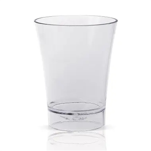
The nozzle layout design needs to be optimized based on the part’s shape and temperature distribution to ensure uniform cooling. For circular, deep-cavity parts (such as cups and buckets), a main nozzle can be placed at the center of the cavity bottom, with 3-4 auxiliary nozzles evenly spaced circumferentially around the sidewalls. The main nozzle is responsible for cooling the bottom, while the auxiliary nozzles are responsible for cooling the sidewalls, keeping the temperature difference between different parts of the cavity within 5°C. For rectangular, thin-walled parts (such as mobile phone cases), a matrix nozzle layout is required, with each nozzle responsible for a cooling area of 10×10mm², and nozzle spacing of 15-20mm to ensure that the jet stream covers the entire cavity surface. For complex parts with ribs and bosses, dedicated nozzles are required at the base of the ribs and the base of the bosses. These areas often experience severe heat accumulation and require enhanced cooling intensity. For example, a 2mm diameter nozzle can be placed at the base of a 5mm diameter boss to improve local cooling efficiency.
The process parameters of the jet cooling channel must be matched to the injection molding process, achieving optimal cooling results through precise control of pressure, flow, and temperature. The jet pressure setting should be adjusted according to the thermal conductivity of the plastic part material and the cavity depth. For plastics with low thermal conductivity (such as PC and ABS), a higher pressure (0.6-0.8 MPa) is required to enhance convective heat transfer; for plastics with high thermal conductivity (such as PE and PP), a lower pressure (0.3-0.5 MPa) can be used to avoid energy waste. The coolant inlet temperature is generally 15-25°C, and the temperature difference between the outlet and inlet temperatures is controlled within 5-8°C. The flow rate is controlled by a flow control valve (usually a proportional valve) to ensure uniform flow rate across each nozzle (error ≤5%). During the injection molding process, the jet cooling system must be synchronized with the injection molding machine cycle. Jet injection starts immediately after melt filling is completed, maintains high injection speed during the holding pressure phase, and gradually reduces pressure during the cooling phase to avoid sudden drops in cavity temperature that can increase internal stress in the plastic part.
The installation and maintenance of jet cooling channels are crucial to ensuring effective cooling. Attention must be paid to sealing performance, anti-clogging design, and regular cleaning. The connection between the nozzle and the mold must be sealed with an O-ring (made of fluororubber, temperature resistant ≥150°C) to prevent coolant leakage and affect the life of other mold components (such as guide pins and ejector pins). A filter (50-100μm) should be installed at the nozzle inlet to prevent impurities in the water from clogging the nozzle. The filter should be cleaned weekly to ensure smooth flow. After long-term use, scale deposits on the cavity surface may affect heat transfer. Regularly circulate a descaling agent (such as citric acid solution) through the entire cooling system at least annually to remove scale and biosludge. Furthermore, nozzles should be regularly inspected for wear and tear. Any deformation or corrosion of the nozzle tip should be promptly replaced to ensure stable jet shape and velocity for efficient cooling performance.