Injection molding of springs between movable plates
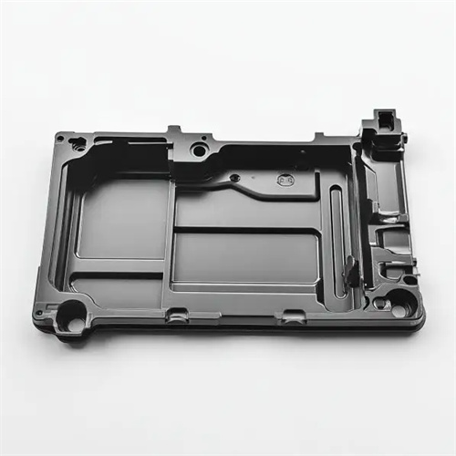
The springs between the movable plates in injection molding are key elastic components used in molds to achieve functions such as resetting, buffering, and pre-tightening the plates. They are widely used in ejector mechanisms, core-pulling mechanisms, and parting surface control. As components that can move relative to each other in the mold, the precision and coordination of the movable plates’ movement directly impact the molding quality of the plastic part and the mold’s service life. By providing continuous elastic force, the springs ensure that the movable plates follow a preset trajectory during mold opening and closing, avoiding motion errors caused by inertia or uneven force. For example, in the ejector mechanism, the spring is installed between the ejector plate and the movable mold base plate. During mold opening, the spring pushes the ejector plate, driving the ejector pin to eject the plastic part. During mold closing, the spring is compressed and reset under the pressure of the mold, ensuring that the ejector pin does not affect the molding of the plastic part.

When selecting the spring between the movable plate in injection molding, parameters such as spring force, compression, and service life must be comprehensively considered to meet different operating requirements. The spring force calculation formula is: F = k × x, where F is the spring force (N), k is the spring constant (N/mm), and x is the compression (mm). When selecting a spring, the minimum spring force required must be determined based on the weight of the movable plate, its resistance to movement, and other factors to ensure the spring can smoothly propel the plate. At the same time, the spring force should not be too high to avoid increasing the mold’s drive load. For example, to push a movable plate weighing 3kg, the friction force to be overcome is approximately 5N. After considering a safety factor, the minimum spring force should be no less than 10N. For a spring with a constant of 2N/mm, the required compression is 5mm. The free length of the spring should be determined based on the maximum travel of the movable plate. The compressed length should not be less than 50% of the free length to avoid permanent deformation of the spring due to excessive compression.
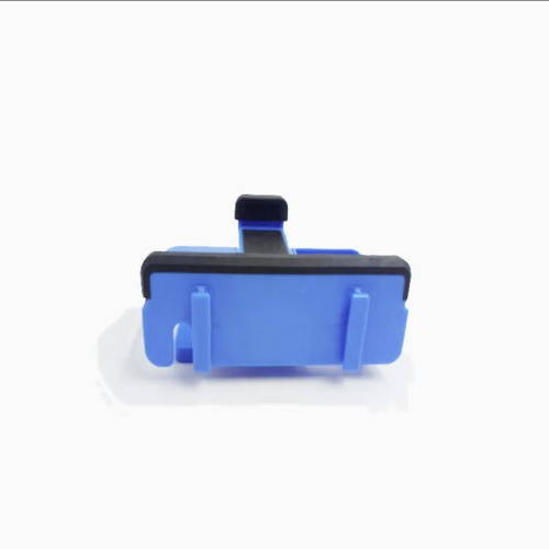
The way the spring is installed between the movable plates is crucial to its performance. Common installation methods include countersunk hole installation, guide post installation, and hook installation. Countersunk hole installation involves machining a countersunk hole on the movable plate that matches the outer diameter of the spring and embedding the spring into it. This method prevents the spring from bending sideways during compression and is suitable for situations where high spring verticality is required. Guide post installation involves setting a guide post inside the spring. The gap between the guide post and the spring is 0.5-1mm, which can effectively guide the direction of spring expansion and contraction and is suitable for movable plates with long strokes. Hook installation connects the spring to the movable plate through hooks at both ends and is suitable for situations where larger elastic deformation is required. For example, the movable plate stroke of a certain mold is 20mm, and a countersunk hole installation method is used. The depth of the countersunk hole is 1/2 of the free length of the spring, ensuring that the spring always remains vertical during compression without bending sideways.
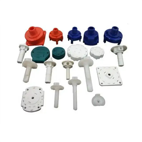
The material selection and heat treatment process for springs directly impact their service life and reliability. Common spring materials used in injection molds are carbon spring steel (such as 65Mn) and alloy spring steel (such as 50CrVA). 50CrVA steel has high fatigue strength and heat resistance, making it suitable for applications with high operating temperatures (over 100°C) or long service life requirements (over 100,000 cycles). 65Mn steel, on the other hand, is less expensive and suitable for room-temperature operation and light loads. Springs require quenching and intermediate-temperature tempering to a hardness of HRC 45-50, ensuring excellent elasticity and toughness. For example, in a PA66+GF mold, the operating temperature of the spring between the movable plates can reach 120°C. A spring made of 50CrVA steel can achieve a service life of over 300,000 cycles, while a spring made of 65Mn steel will experience a loss of elasticity after 100,000 cycles.
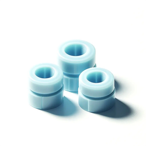
In practical applications, appropriate solutions are needed to address common problems with springs between movable plates in injection molding. Spring breakage is often caused by excessive compression due to insufficient elastic force, or lateral bending stress caused by improper installation. This can be addressed by replacing the spring with a larger size or optimizing the installation method. Spring force loss may be due to material fatigue or excessively high operating temperatures, requiring the use of higher-strength materials or increasing the number of springs. Spring corrosion is primarily caused by the mold’s humid working environment; the springs can be galvanized or chrome-plated to improve their corrosion resistance. For example, a mold factory in a coastal area discovered that the springs between the movable plates were prone to rust. After chrome plating, the rust condition was significantly improved, and the service life was doubled. Furthermore, regular inspection and maintenance of the springs, and the timely replacement of aging or damaged springs, can ensure the normal movement of the movable plates and improve the overall reliability of the mold.