Composite demoulding of movable mold push plate and movable mold push rod
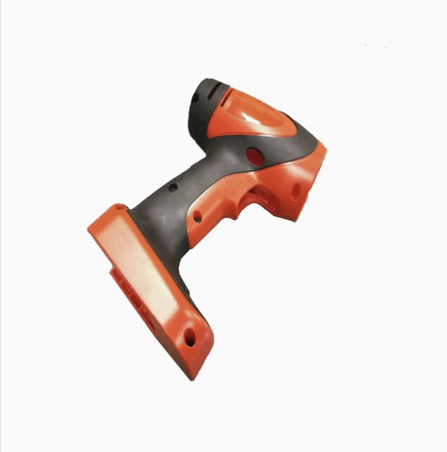
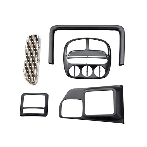
The combined ejection mechanism of a movable mold plate and ejector rod is a highly efficient demolding solution designed for complex plastic parts. Through the coordinated action of the ejector plate and ejector rod, it solves the demolding challenges of deep-cavity, thin-walled, and multi-ribbed parts, which are difficult to address with a single demolding method. This mechanism combines the advantages of the ejector plate’s uniform ejection force with the ejector rod’s targeted demolding capabilities, achieving fast and smooth demolding without deforming the part. It is widely used in the production of precision plastic parts such as automotive parts and appliance housings.
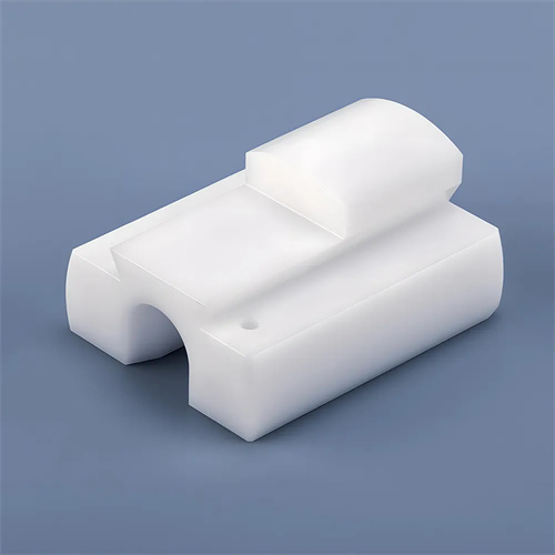
The structure of the composite demolding mechanism is relatively sophisticated, primarily consisting of a movable mold push plate, a push rod fixing plate, push rods, a return spring, a guide column, and a limit device. The movable mold push plate covers a large area of the plastic part, typically forming a tight fit with the core and bearing the primary clamping force of the plastic part. The push rods are positioned at localized, concentrated stress points, such as ribs and bosses, based on the structural characteristics of the plastic part, to provide targeted ejection force. The push rod fixing plate connects multiple push rods together to ensure their synchronous movement. The return spring pushes the push plate and push rods back to their initial position after demolding. The guide column ensures the coaxiality of the push plate and push rods to prevent jamming. The limit device controls the demolding stroke to prevent damage to the plastic part due to excessive ejection. For example, in the composite demolding mechanism for a deep-cavity shell plastic part, the push plate is responsible for pushing the edge of the plastic part, while six push rods push the reinforcing ribs inside the shell. The two work together to evenly distribute the demolding force.
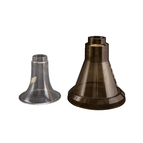
The combined demolding process is divided into three stages. During the initial mold opening, the ejector pushes the push rod fixing plate, driving the push rod and movable mold push plate forward synchronously. At this point, the push plate and push rod work together to initially lift the part from the core, overcoming most of the clamping force. When the push plate reaches the set travel (usually 1/3 of the part’s height), a limiter stops the push plate, while the push rod continues to push against a localized area of the part, completely freeing it from the core. After demolding is complete, the return spring resets the push rod and push plate, ready for the next injection cycle. This step-by-step demolding method avoids stress concentration during single demolding and is particularly suitable for parts with widely varying wall thicknesses, such as a part with a thickness gradient from 2mm to 8mm. The push plate first relieves stress in the thin-walled areas, while the push rod then pushes against the thicker areas, effectively preventing cracking in the part.
Key design considerations for the composite demolding mechanism lie in motion coordination and force balance. The sequence of movement of the push plate and push rod must be precisely controlled by limiters. Generally, the push plate’s demolding stroke is two-thirds of the part’s height, while the push rod’s additional stroke is one-third, ensuring even support throughout the demolding process. Push rod placement should adhere to the “proximity principle,” with increased push rod density located at locations farthest from the core. For example, for a 500mm diameter round part, one push rod should be placed every 100mm along the edge, with 3-4 more in the center to complement the push plate. The clearance between the push plate and the core must be controlled within 0.05-0.1mm to ensure smooth movement while preventing plastic melt from overflowing into the gap between the push plate and the core, forming flash. Furthermore, the push plate and push rod should be made of high-strength alloy steel (such as SKD61), hardened to HRC50-55 to withstand the repeated impact of demolding.
The debugging and optimization of the composite demolding mechanism must be conducted in conjunction with trial mold data. During trial molds, the demolding posture of the plastic part must be carefully observed. If the push plate and push rod move out of sync, the clearance between the guide post and the hole may be excessive, and a more precise guide assembly may be required. If push plate marks appear on the part surface, the push plate’s push pressure should be reduced while the push rod’s ejection force should be increased. For parts prone to mold sticking (such as POM), a 0.5mm deep vent groove can be created on the push plate’s contact surface to dissipate the vacuum generated during demolding. The return spring’s tension should be regularly checked during production and replaced promptly if it decreases by more than 20% to prevent mold failure caused by incomplete reset. Finite element simulation analysis of stress distribution during demolding can further optimize the push plate thickness and push rod diameter. For example, one simulation revealed stress concentration at the push plate’s edge. By increasing the push plate’s thickness by 2mm and adding a rounded transition at the edge, the stress was reduced by 30%.

Maintenance of the composite demolding mechanism is crucial to extending mold life. Before daily production, check the movement flexibility of the push rod and push plate, and apply high-temperature grease to reduce friction. Disassemble and clean the mating surfaces of the push plate and core weekly to remove plastic residue and oil stains. Measure the wear of the push rod monthly and replace it promptly if the diameter decreases by more than 0.1mm. For mass-produced molds, wear-resistant gaskets (such as carbide) can be installed on the end of the push rod to reduce the rate of wear. With the development of intelligent molds, some composite demolding mechanisms have integrated pressure sensors to monitor the force applied to the push plate and push rod in real time. When the force fluctuation exceeds ±5%, an automatic alarm is triggered, prompting the operator to check and adjust, further improving production stability.