Rack and pinion arc core pulling mechanism
The rack-and-pinion arc core-pulling mechanism is a key device in injection molds, used to solve the demolding problem of plastic products with arc-shaped lateral protrusions or depressions. Through the meshing transmission of the gear and rack, it converts linear motion into circular motion, enabling precise core extraction. It is widely used in the production of complex plastic parts such as automotive parts and medical devices. The rationality of this mechanism’s design directly affects the molding quality, production efficiency, and mold life of the plastic part. Therefore, systematic optimization is required in terms of structural composition, transmission accuracy, and material selection.
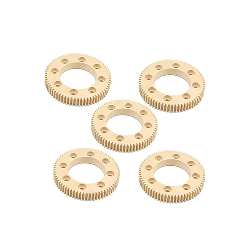
The core components of the rack and pinion arc core-pulling mechanism include a rack drive, gears, an arc core, a guide, and a locking mechanism. The rack drive is usually connected to the ejection system of the injection molding machine, providing linear driving force during mold opening. The gear and rack are tightly meshed, converting linear motion into circular motion, which in turn drives the arc core fixed to the gear to perform an arc core-pulling motion. The guide device often uses a combination of sliders and guide grooves to ensure that the gear and rack maintain the correct meshing clearance during movement to avoid jamming or offset. The locking mechanism firmly fixes the arc core during the mold closing and injection stage to prevent core displacement due to melt pressure. Common locking methods include wedge block locking and hydraulic locking. In addition, to reduce wear during the transmission process, the meshing surfaces of the gear and rack are subjected to high-frequency quenching to a hardness of HRC50-55, and are coated with high-temperature grease to reduce the coefficient of friction.
The working process of this mechanism can be divided into four stages: mold closing and locking, injection molding, mold opening and core pulling, and ejection and demolding. During mold closing, the mold cavity and core are closed under the driving force of the injection molding machine, and the locking mechanism fixes the arc core in the molding position. At this time, the gear and rack are in the initial meshing state. During the injection molding stage, the plastic melt fills the mold cavity under high pressure, and the arc core is subjected to the lateral pressure of the melt. The locking mechanism must provide sufficient clamping force to resist this pressure. During mold opening, the injection molding machine drives the movable mold backward, and the rack drive moves with the movable mold. Through the meshing transmission of the gear and rack, the arc core is slowly pulled away from the plastic part along a preset arc trajectory. After the core is pulled, the ejection mechanism is activated to eject the plastic part from the main core, completing the entire demolding process. It is worth noting that the core pulling speed needs to be controlled by adjusting the movement speed of the rack drive, generally controlled at 50-100mm/s to avoid scratches or deformation on the plastic part surface due to excessive speed.
Key design considerations for a rack-and-pinion circular core-pulling mechanism lie in determining the transmission ratio and avoiding motion interference. This transmission ratio must be calculated based on the core-pulling angle of the arc core and the effective rack travel. For example, when the core-pulling angle is 60°, the pitch diameter of the gear and the rack travel must maintain a specific ratio to ensure the core accurately reaches the core-pulling endpoint. Simultaneously, the mechanism’s motion trajectory must be simulated and analyzed using 3D modeling software to check for interference between the rack and gear and other mold components during movement. This is particularly important at the start and end points of the core-pulling operation, where a minimum clearance of 5mm must be maintained. Furthermore, the radius of curvature of the arc core must perfectly match the arc characteristics of the plastic part, and the molded surface roughness must be controlled below Ra0.8μm to ensure surface quality. For applications with longer core-pulling distances, a dual-pinion transmission structure can be employed, with the addition of an intermediate gear to extend the effective rack drive travel and improve transmission stability.
In practice, the rack-and-pinion arc core-pulling mechanism requires targeted optimization based on the specific structure of the plastic part. For parts with multiple arc features, multiple rack-and-pinion mechanisms can be designed, enabling coordinated core pulling of multiple cores via timing belts or interlocking shafts, ensuring consistent core pulling speeds and angles across all cores. Large arc cores require support bearings at both ends of the gear shaft to minimize shaft diameter deformation caused by cantilever forces. For molds operating in high-temperature environments (such as those molding PA66+GF materials), gears and racks must be constructed from high-temperature-resistant alloys to prevent changes in meshing clearance due to temperature fluctuations. Regular maintenance is also crucial to maintaining mechanism performance. Monthly check of rack-and-pinion meshing clearance (maintained within 0.03-0.05mm), quarterly grease replacement, and annual replacement of severely worn components are essential to ensure transmission accuracy and longevity.