Calculation of demoulding force during core pulling
During the injection molding process, calculating the ejection force during the core pulling process is a critical step in mold design. Its value directly determines the driving force of the core pulling mechanism, component strength, and the selection of the power source. The ejection force refers to the force required to extract the core from the plastic part. It is primarily composed of the friction between the part and the core, the holding force generated by the shrinkage of the plastic part, and the resistance to deformation of the plastic part during the core pulling process. Accurately calculating the ejection force can avoid core pulling difficulties or part damage caused by insufficient driving force, while also preventing energy waste and mechanical wear caused by excessive driving force. Therefore, it is necessary to establish a scientific calculation model that comprehensively considers multiple influencing factors.

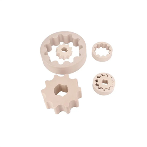
The holding force between the part and the core is the primary component of the demolding force. Its magnitude is closely related to the part’s shrinkage, molding area, and melt pressure. Plastic shrinks during cooling, generating a radial holding force on the core. The calculation formula is: Fhold = K × A × P × μ, where K is the shrinkage coefficient (depending on the plastic type; for example, the K value for PP is 0.8-1.2), A is the contact area between the part and the core (in mm²), P is the unit pressure exerted by the part on the core (generally 5-15 MPa), and μ is the coefficient of friction (the friction coefficient between a steel core and plastic is typically 0.1-0.3). For example, when the contact area between the part and the core is 1000 mm² and the unit pressure is 10 MPa, the holding force can reach 800-3600 N. In addition, for cores with concave and convex patterns, the holding force will increase significantly due to the increased contact area and mechanical bite, and a correction factor of 1.5-2.0 must be multiplied when calculating.
The calculation of friction must consider the surface roughness of the core and the surface condition of the molded part. The smoother the core surface, the lower the friction. Therefore, the core molding surface roughness is typically required to be below Ra0.8μm. However, burrs or flash on the part surface increase frictional resistance , so appropriate venting grooves and parting surfaces should be incorporated into the mold design to minimize these defects. The formula for calculating friction is: Ffriction = Fhold × cosθ, where θ is the core draft angle. A larger draft angle decreases the cosθ value and reduces friction. Therefore, a draft angle of 3°-5° should be used when designing the core to minimize demolding difficulty. For example, when the holding force is 2000N and the draft angle is 3°, the friction is approximately 1997N. Increasing the draft angle to 5° reduces the friction to 1992N. While this reduction is small, it can significantly reduce wear on the mechanism over long-term production.
The deformation resistance of plastic parts cannot be ignored during the core pulling process, especially for thin-walled or slender parts. Uneven force during core pulling can easily cause deformation, which in turn increases the demolding force. The magnitude of this deformation resistance is related to the part’s elastic modulus, thickness, and core pulling speed. The lower the elastic modulus (e.g., PE, PP), the greater the deformation resistance. Thinner parts are more susceptible to bending and deformation during core pulling, leading to localized stress concentration and increased demolding difficulty. Finite element analysis can be used to calculate deformation resistance. By simulating the stress distribution of the part during core pulling, the resistance value in the area of maximum deformation can be determined. Generally speaking, deformation resistance accounts for 10%-20% of the total demolding force. For example, for a thin-walled PP part with a thickness of 1mm, its deformation resistance is approximately 15% of the total demolding force. This force must be factored into the total demolding force calculation.

The calculation of the total demolding force requires integrating the values of the aforementioned forces and factoring in a safety factor. Total demolding force Ftotal = (Fhold + Ffriction + Fchange) × KAn, where KAn is the safety factor. This value is determined based on the criticality of the part and is generally between 1.2 and 1.5, with a range of 1.5 to 2.0 for high-precision parts. In actual application, the calculated results must be verified and corrected through trial molds. For example, if core pulling is difficult during trial molds, the safety factor can be appropriately increased or the driving force of the core pulling mechanism can be optimized. If excessive driving force causes whitening on the part surface, the calculation model should be reviewed and any unnecessary safety margins reduced. Furthermore, the calculation of the demolding force must be adjusted based on the core pulling method (e.g., linear vs. circular). Due to the radial force component in circular core pulling, the total demolding force should be multiplied by a correction factor of 1.1 to 1.3 to ensure the accuracy of the calculated results.